Concrete Pipe Flow Chart
The Importance of Understanding Concrete Pipe Flow Chart
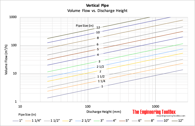
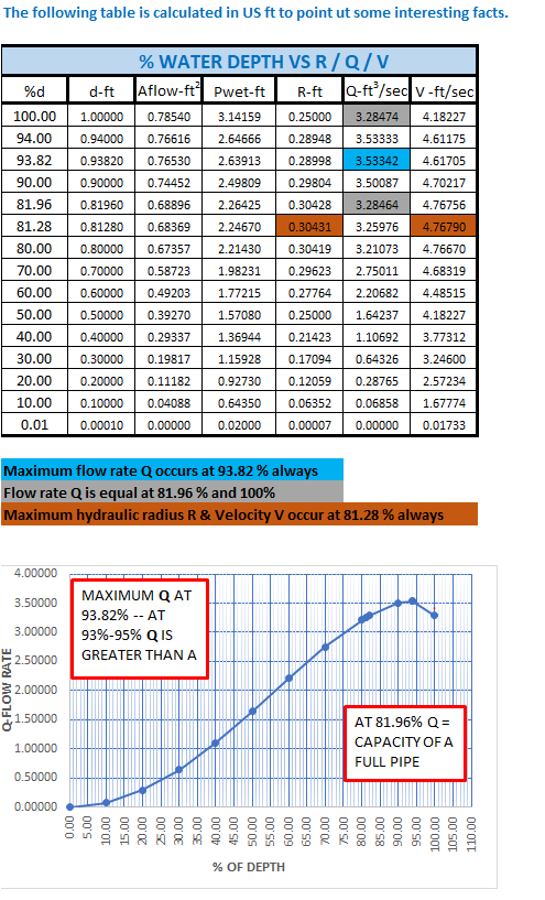
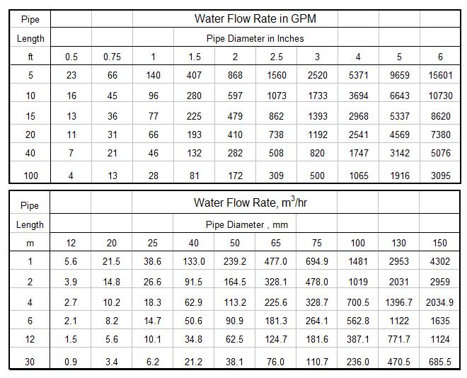
Concrete pipes are essential components in various construction projects, such as sewer systems, drainage systems, and stormwater management. To ensure the proper functioning of these systems, it is crucial to understand the flow characteristics of concrete pipes. A concrete pipe flow chart provides valuable information on the flow capacity of different pipe sizes and shapes, helping engineers and contractors design efficient and reliable infrastructure.
Benefits of Using a Concrete Pipe Flow Chart
One of the key benefits of using a concrete pipe flow chart is that it allows for accurate sizing and selection of pipes based on the expected flow rates. By referencing the flow chart, engineers can determine the optimal pipe diameter and slope to achieve the desired flow capacity while minimizing the risk of blockages or overflows. This not only ensures the smooth operation of the system but also helps reduce maintenance and repair costs in the long run.
Additionally, a concrete pipe flow chart can help in optimizing the design of stormwater management systems to prevent flooding and erosion. By following the guidelines provided in the flow chart, designers can create efficient drainage networks that can handle varying flow rates and volumes during heavy rain events. This is particularly important in urban areas where stormwater runoff can cause significant damage to infrastructure and the environment if not properly managed.
Challenges in Using Concrete Pipe Flow Chart
Despite its benefits, using a concrete pipe flow chart can be challenging for those who are not familiar with hydraulic engineering principles. Understanding terms such as flow velocity, pipe roughness, and head loss can be daunting for beginners, making it difficult to interpret the information presented in the flow chart accurately. To overcome this challenge, it is essential to seek guidance from experienced professionals or consult resources that provide detailed explanations of the various parameters involved in pipe flow calculations.
Conclusion
In conclusion, a concrete pipe flow chart is a valuable tool for designing and analyzing drainage and sewer systems. By utilizing the information provided in the flow chart, engineers and contractors can ensure the proper sizing and selection of pipes to meet the required flow capacity. While there may be challenges in interpreting the data presented in the flow chart, seeking assistance from knowledgeable experts can help overcome these obstacles and optimize the performance of concrete pipe systems. Ultimately, understanding and utilizing a concrete pipe flow chart can lead to more efficient and sustainable infrastructure projects.
Download Concrete Pipe Flow Chart
Maximum Flow Through Pipe Chart
Gravity Pipe Flow Chart
Pipe Size Flow Chart
PVC Pipe Process Flow Chart


